

Ask about this document
The AI answers using only this document and cites its pages.
AI Mode
Document preview
The answer was cut off before it finished.
You stopped the answer.
There are no documents for this question with the selected filters.
What went wrong?
Conversation about Fagor documentation
The answer was cut off before it finished.
You stopped the answer.
There are no documents for this question with the selected filters.
What went wrong?




Document contents
70 sections- INDEX 3
- 1. CHARACTERISTICS AND CONNECTION. 5
- 1.1 HBG 800-DP handwheel. 7
- 1.2 HBG 800-DP access point. 8
- 1.3 Charging station. 9
- 1.4 Support for the charging station. 9
- 1.5 Connecting adaptor HBG 800-DP FS. 10
- 1.5.1 S1 Switch - PROFIBUS Address. 11
- 1.5.2 X1 Connector - PROFIBUS interface. 11
- 1.5.3 Connector X2 - Emergency signals, enabling and power 24 V. 11
- 1.5.4 Connector X3 - Access point connection. 12
- 1.5.5 Connector X4 - Access point connection. 12
- 1.5.6 Connector X5 - Outputs for PLC safety. 12
- 1.5.7 Connector X6 - Access point connection. 12
- 1.6 Response time of the HBG 800-DP FS system. 12
- 1.7 Anybus X-gateway (Master PROFIBUS - Slave EtherCAT). 13
- 1.7.1 Dimensions. 14
- 1.7.2 Connector X1.1 - PROFIBUS connector (9-pin female Sub-D). 15
- 1.7.3 Connector X1.2 - PROFIBUS configuration (9-pin male Sub-D). 15
- 1.7.4 X3 connector - Power supply connector. 15
- 1.7.5 Port 1 (Input) and Port 2 (Output) of EtherCAT. 15
- 1.7.6 LED indicators (PROFIBUS). 16
- 1.7.7 LED indicators (EtherCAT). 16
- 1.8 (SNR-10-223-DT) DC Filter. 17
- 1.8.1 Dimensions. 17
- 1.9 Toroidal core (KEMET ESD-SR-250). 18
- 1.9.1 Dimensions and characteristics of the toroidal core. 18
- 1.10 System installation. 19
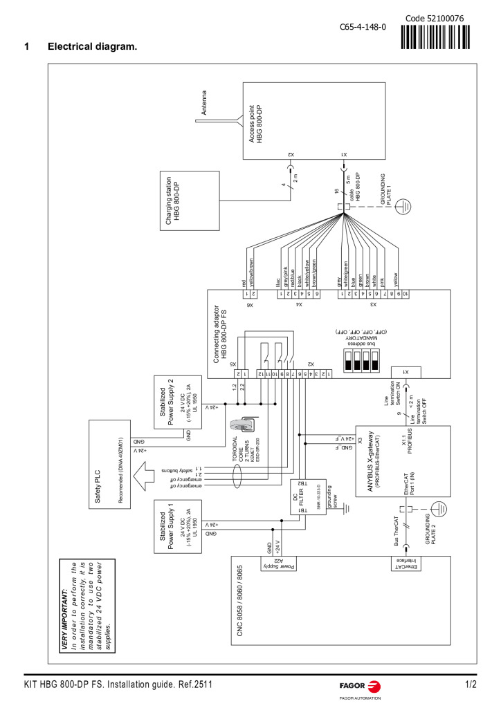
- 1.11 Electrical diagram. 23
- 2. PARAMETER SETTING AND START- UP. 25
- 2.1 Configuration of the HBG 800-DP handwheel. 25
- 2.1.1 Keys and push buttons used to configure the handwheel. 25
- 2.1.2 Access the configuration menu. 25
- 2.1.3 Change configuration. 26
- 2.1.4 Description of menu items. 26
- 2.1.5 Test routines. 27
- 2.1.6 General description of the configuration. 27
- 2.1.7 Handwheel configuration process. 28
- 2.1.8 Actions to avoid interruptions. 29
- 2.1.9 Frequency table. 29
- 2.1.10 Access point LEDs. 30
- 2.1.11 Connection adapter LEDs. 30
- 2.2 Configuration of the Anybus X-gateway. 31
- 2.2.1 Connected to carry out gateway configuration. 31
- 2.2.2 Configuration of master and slave address. 32
- 2.2.3 PROFIBUS Configuration. 33
- 2.2.4 PROFIBUS Master configuration. 34
- 2.2.5 EtherCAT slave configuration. 34
- 2.2.6 Generation of ESI file. 35
- 2.3 CNC configuration. 36
- 2.3.1 Machine parameters. 36
- 2.3.2 Integration of the KIT HBG 800-DP FS Handwheel files into the PLC. 37
- 2.3.3 Messages and errors from the KIT HBG 800-DP FS Handwheel. 37
- 2.3.4 Integration of the Anybus X-gateway into the EtherCAT bus. 38
- 3. DESCRIPTION OF KEYS AND OPERATION. 39
- 3.1 Keys and push buttons on the HBG 800-DP handwheel. 39
- 3.1.1 Safety devices. 39
- 3.1.2 Handwheel and potentiometers SPEED and FEED. 40
- 3.1.3 LEDs on the keypad. 40
- 3.1.4 Keypad and LCD screen. 41
- 3.2 Turning the HBG 800-DP handwheel on and off. 42
- 4. TROUBLESHOOTING AND MAINTENANCE. 43
- 4.1 Error solution. 43
- 4.1.1 Possible errors. 43
- 4.1.2 Cause of errors. 43
- 4.1.3 Low battery screen. 44
- 4.1.4 The handwheel is not working. 44
- 4.2 Maintenance and care. 45
- 4.2.1 Handwheel not used for an extended period. 45
- 4.2.2 Replacement of rechargeable batteries. 45
Related documentation
See all in Manuals
CNCelite 8065 Cylindrical grinder manual (·G· model)
PDF 9.3 MB · EN

CNCelite 8065 Gear hobbing machine manual (·G· model)
PDF 3.4 MB · EN ES

CNCelite 8065 Surface grinding machine manual (·G· model)
PDF 3.5 MB · EN
KIT HBG 800-DP FS. Quick Reference
PDF 0.2 MB · EN
Log in to download
New to the platform?
Create an account
·
