
Product documentation
Absolute angular encoder without integrated bearings – Serie UT
CatalogueAngular encoder without integral bearings for angular position measurements: The system comprises two components: the reader head and a stainless steel ring with the engraved graduation: Motor does not require a higher torque to start rotating as the encoder is contact-less and without sealings between the parts. It may need additional protection to reach the IP required by the application. The modular system allows, if needed, for a quick and easy maintenance in comparison with other solutions with the encoder integrated in one system. Only one absolute track with patented 3STATECH technology. Homing immediately after powering on the machine without moving the axis. The digital communication provides the position to the control system at high angular velocity. Excellent features together with the CNC system enable a smooth and reliable position control. Large mounting tolerances: easy alignment and assembly. Designed for applications such as semiconductor manufacturing equipment, testing and measuring systems, printers, rotary tables, as well as integration with rotary motors (typically C axis in lathes) or with DD (Direct Drive) motors.
22 documents Product page
Exposed encoders EN
- Absolute angular encoder without integrated bearings – Serie UT · Linear absolute EN
- Exposed linear absolute encoders · Linear absolute EN
- Non-contact linear absolute encoders – EXA · Linear absolute EN
- Non-contact linear absolute encoders – EXG · Linear absolute EN
- Non-contact linear absolute encoders – EXT · Linear absolute EN
- Non-contact linear incremental encoders – ITA · Linear absolute EN
- Non-contact linear incremental encoders – ITG · Linear absolute EN
- Non-contact linear incremental encoders – ITT · Linear absolute EN
- Exposed linear incremental encoders · Linear incremental
Catalogs
1


Manuals
7-
 Additional Information DRIVE-CliQ adapters
PDF 0.2 MB

-
 DRIVE-CliQ extension adapter
PDF 0.4 MB
-
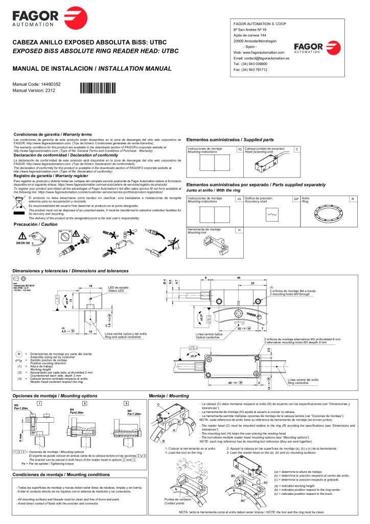 UT model absolute angular encoder without integral bearings – BiSS C protocol reader head
PDF 0.4 MB
-
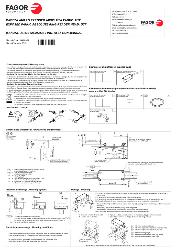
-
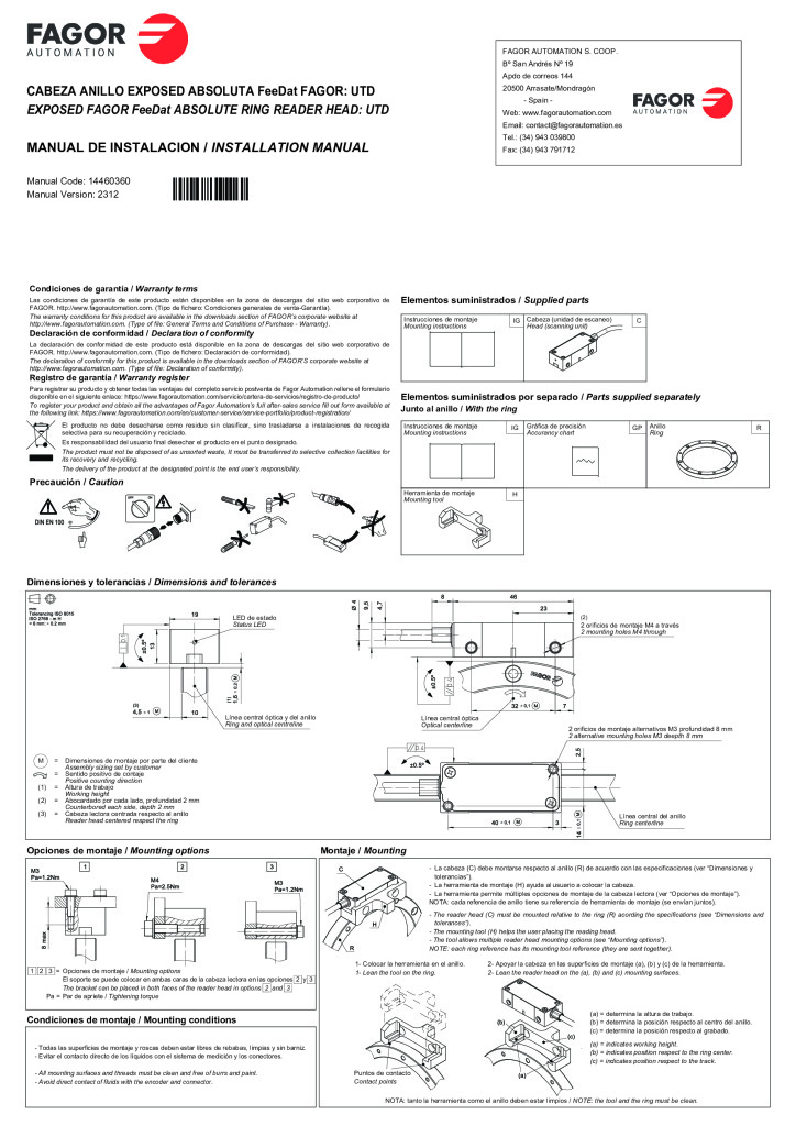 UT model absolute angular encoder without integral bearings – FeeDat (Fagor) protocol reader head
PDF 0.4 MB
-
 UT model absolute angular encoder without integral bearings – Panasonic protocol reader head
PDF 0.4 MB
-
CAD drawings
13-
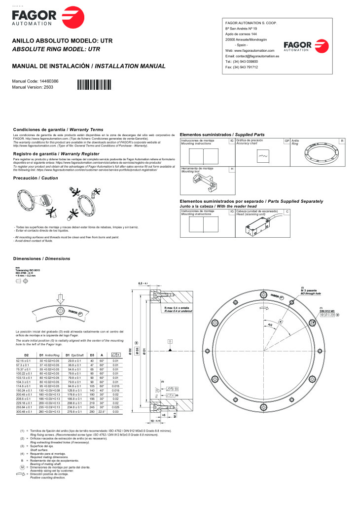
UTR-D100i80 – ring
ZIP 32 KB

-
UTR1-D103i80 – ring
ZIP 0.3 MB
-
UTR1-D104i80 – ring
ZIP 0.3 MB
-
UTR1-D115i95 – ring
ZIP 0.3 MB
-
UTR1-D150i130 – ring
ZIP 0.3 MB
-
UTR1-D200i180 – ring
ZIP 0.3 MB
-
UTR1-D209i186 – ring
ZIP 63 KB
-
UTR1-D229i209 – ring
ZIP 0.3 MB
-
UTR1-D255i235 – ring
ZIP 0.3 MB
-
UTR1-D300i280 – ring
ZIP 0.4 MB
-
UTR1-D52i30 – ring
ZIP 0.3 MB
-
UTR1-D57i37 – ring
ZIP 0.3 MB
-
UTR1-D75i55 – ring
ZIP 0.3 MB
Declaration of conformity
1
Manual contents
UT model absolute angular encoder without integral bearings – FeeDat (Fagor) protocol reader head
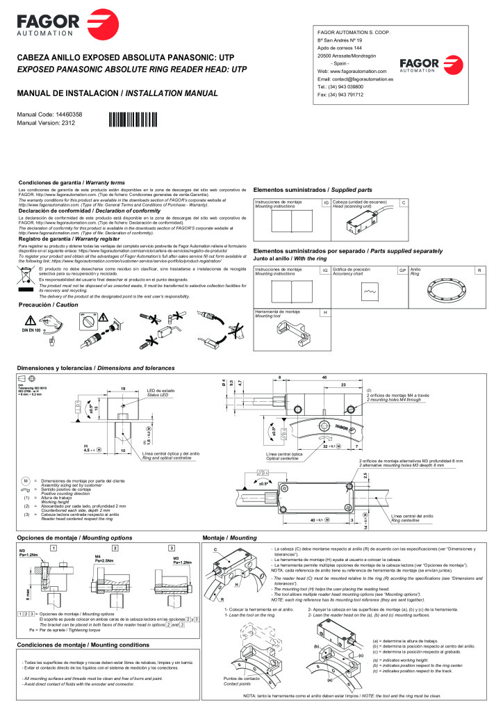
- Dimensiones y tolerancias / Dimensions and tolerances p. 1
- Opciones de montaje / Mounting options Montaje / Mounting p. 1
- Condiciones de montaje / Mounting conditions p. 1
- Instrucciones de montaje p. 1
- Mounting instructions p. 1
- Cabeza (unidad de escaneo) p. 1
- Head (scanning unit) p. 1
- IG p. 1
- C p. 1
- Instrucciones de montaje p. 1
- Mounting instructions p. 1
- Gráfica de precisión p. 1
- Accurancy chart p. 1
- IG p. 1
- GP p. 1
- Anillo p. 1
- Ring p. 1
- R p. 1
- Herramienta de montaje p. 1
- Mounting tool p. 1
- H p. 1
- LED de estado p. 1
- Status LED p. 1
- Línea central óptica y del anillo p. 1
- Ring and optical centreline p. 1
- (2) p. 1
- 2 orificios de montaje M4 a través p. 1
- 2 mounting holes M4 through p. 1
- Línea central óptica p. 1
- Optical centerline p. 1
- 2 orificios de montaje alternativos M3 profundidad 8 mm p. 1
- 2 alternative mounting holes M3 deepth 8 mm p. 1
- M = Dimensiones de montaje por parte del cliente p. 1
- Assembly sizing set by customer p. 1
- = Sentido positivo de contaje p. 1
- Positive counting direction p. 1
- (1) = Altura de trabajo p. 1
- Working height p. 1
- (2) = Abocardado por cada lado, profundidad 2 mm p. 1
- Counterbored each side, depth 2 mm p. 1
- (3) = Cabeza lectora centrada respecto al anillo p. 1
- Reader head centered respect the ring p. 1
- Línea central del anillo p. 1
- Ring centerline p. 1
- 1 2 3 = Opciones de montaje / Mounting options p. 1
- El soporte se puede colocar en ambas caras de la cabeza lectora en las opciones 2 y 3 p. 1
- The bracket can be placed in both faces of the reader head in options 2 and 3 p. 1
- Pa = Par de apriete / Tightening torque p. 1
- - Todas las superficies de montaje y roscas deben estar libres de rebabas, limpias y sin barniz. p. 1
- - Evitar el contacto directo de los líquidos con el sistema de medición y los conectores. p. 1
- - All mounting surfaces and threads must be clean and free of burrs and paint. p. 1
- - Avoid direct contact of fluids with the encoder and connector. p. 1
- - La cabeza (C) debe montarse respecto al anillo (R) de acuerdo con las especificaciones (ver “Dimensiones y tolerancias”). p. 1
- - La herramienta de montaje (H) ayuda al usuario a colocar la cabeza. p. 1
- - La herramienta permite múltiples opciones de montaje de la cabeza lectora (ver “Opciones de montaje”). p. 1
- NOTA: cada referencia de anillo tiene su referencia de herramienta de montaje (se envían juntos). p. 1
- - The reader head (C) must be mounted relative to the ring (R) acording the specifications (see “Dimensions and tolerances”). p. 1
- - The mounting tool (H) helps the user placing the reading head. p. 1
- - The tool allows multiple reader head mounting options (see “Mounting options”). p. 1
- NOTE: each ring reference has its mounting tool reference (they are sent together). p. 1
- 1- Colocar la herramienta en el anillo. p. 1
- 1- Lean the tool on the ring. p. 1
- 2- Apoyar la cabeza en las superficies de montaje (a), (b) y (c) de la herramienta. p. 1
- 2- Lean the reader head on the (a), (b) and (c) mounting surfaces. p. 1
- (a) = determina la altura de trabajo. p. 1
- (b) = determina la posición respecto al centro del anillo. p. 1
- (c) = determina la posición respecto al grabado. p. 1
- (a) = indicates working height. p. 1
- (b) = indicates position respect to the ring center. p. 1
- (c) = indicates position respect to the track. p. 1
- Puntos de contacto p. 1
- Contact points p. 1
- NOTA: tanto la herramienta como el anillo deben estar limpios / NOTE: the tool and the ring must be clean. p. 1
- Estado de la cabeza / Head status p. 2
- Características eléctricas / Electrical characteristics p. 2
- Montaje rígido con fijaciones. p. 2
- Rigid mounting with clamps. p. 2
- La cabeza lectora tiene un LED para mostrar el estado de la misma. p. 2
- The reader head has a LED to show its status. p. 2
- Flexionado común. p. 2
