
Product documentation
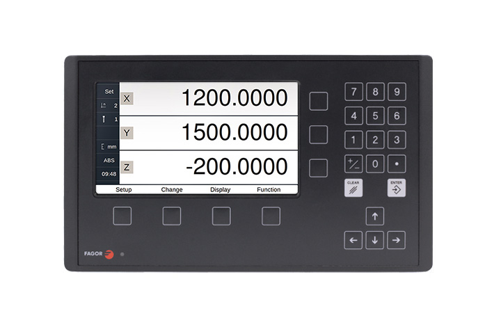
DRO 400i for general purpose applications
CatalogueDRO for grinders and general purpose applications: Innova 400i Preset function Absolute, Incremental and Io reference (home) signals Resolutions from 0.1 microns on Feedrate and movement alarms Axis coupling Hysteresis factor Linear axis sag compensation Calculator function Easy setup and diagnosis Energy saving mode Software limits Multi-point compensation PC communication through a USB adapter Go to a particular position Axis feedrate display On-screen guided help, with graphics CE and UL certified 7" color screen
7 documents Product page
DRO Systems
- DRO 10i for general purpose applications · DRO for general purpose applications
- DRO 20i for general purpose applications · DRO for general purpose applications
- DRO 400i for general purpose applications · DRO for general purpose applications
- DRO 10i for EDM · DROs for EDM
- DRO 20i for EDM · DROs for EDM
- DRO 30i for EDM · DROs for EDM
- DRO 20i for lathes · DROs for lathes
- DRO 30i for lathes · DROs for lathes
- DRO 400i – TS for lathes · DROs for lathes
- DRO 400i for lathes · DROs for lathes
- DRO 20i for milling machines and broing mills · DROs for milling machines and boring mills
- DRO 30i for milling machines and boring mills · DROs for milling machines and boring mills
- DRO 400i for milling machines and boring mills · DROs for milling machines and boring mills
- DRO 400i-P for milling machines and boring mills · DROs for milling machines and boring mills
Catalogs
1-
 DRO Readout Screen – 3 and 4 axes
PDF 1.1 MB


Manuals
2-
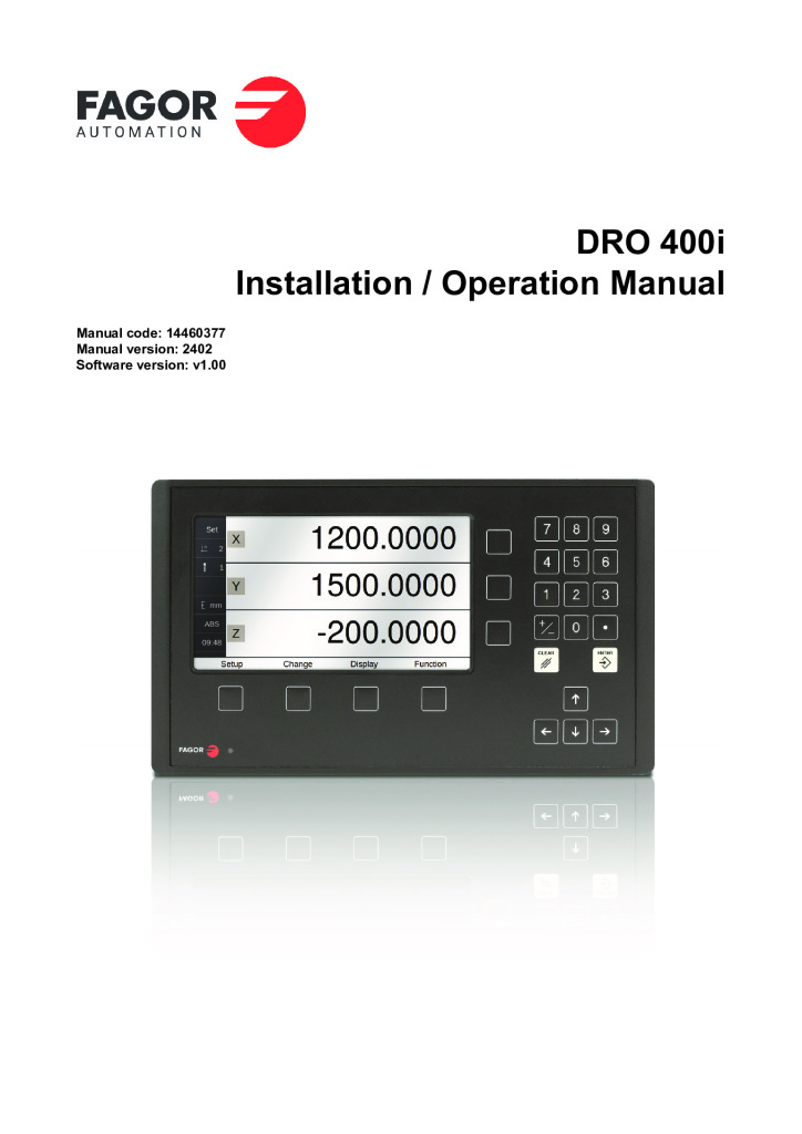 Readout 400i – 3 axis
PDF 3.2 MB
-


CAD drawings
3-
DRO 400i/P/TS
ZIP 1.5 MB

-
 DRO 400i/P/TS 2D MECHANICAL DATA SHEET
PDF 0.9 MB
-
DRO 400i/P/TS-B
ZIP 1.6 MB
Declaration of conformity
1-
 DRO. EC declaration of conformity
PDF 0.2 MB
Manual contents
Readout 400i – 3 axis
- INDEX p. 3
- 1 DRO Description p. 5
- 1.1 Front Plate p. 5
- 1.2 Turning the Unit ON and OFF p. 5
- 1.3 Main Screen Description p. 6
- 1.4 Function Bar p. 6
- 2 DRO Operation in MILL Mode p. 7
- 2.1 Display modes p. 7
- 2.2 Set/Clear p. 8
- 2.3 Machine Reference (Home) Search p. 9
- 2.4 Tools and References p. 9
- 2.5 Special Functions p. 13
- 3 DRO Operation in LATHE Mode p. 19
- 3.1 Display Modes p. 19
- 3.2 Tool p. 20
- 3.3 Special Functions p. 21
- 4 DRO Installation p. 23
- 4.1 Mounting on the Support Arm p. 23
- 4.2 Mounting of the Built-in Model p. 23
- 4.3 Dimensions of the display, the bracket and of the window to insert it into p. 24
- 4.4 Rear Panel p. 25
- 4.5 General Technical Characteristics p. 26
- 4.6 Connections p. 27
- 4.7 Installation Parameters p. 30
- 5 Appendix p. 37
- 5.1 UL/CSA Seal p. 37
- 5.2 CE Seal p. 37
- 5.3 Maintenance p. 39
