
Ask about this document
The AI answers using only this document and cites its pages.
AI Mode
Document preview
The answer was cut off before it finished.
You stopped the answer.
There are no documents for this question with the selected filters.
What went wrong?
Conversation about Fagor documentation
The answer was cut off before it finished.
You stopped the answer.
There are no documents for this question with the selected filters.
What went wrong?


Related products

Document contents
49 sections- INDEX 3
- 1 DRO Description 5
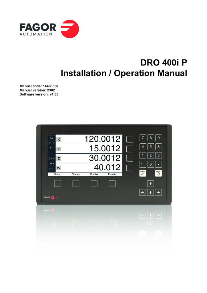
- 1.1 Front Plate 5
- 1.2 Turning the Unit On and Off 5
- 1.3 Main Screen Description 6
- 1.4 Function Bar 6
- 1.4.1 Access to Functions 6
- 2 DRO Operation 7
- 2.1 Display Modes 7
- 2.1.1 mm/inch 7
- 2.1.2 inc/abs 7
- 2.1.3 Rad/Diam 8
- 2.2 Set/Clear 8
- 2.2.1 In "Set" Mode 8
- 2.2.2 In "Clear" Mode 8
- 2.3 Machine Reference (Home) Search 9
- 2.4 Tools and References 9
- 2.4.1 Tools 9
- 2.4.2 Reference 10
- 2.5 Special Functions 13
- 2.5.1 Cycles 13
- 2.5.2 Programs 15
- 2.5.3 Calculator Function 16
- 2.5.4 Simulation/Execution Special Modes 16
- 2.5.5 Probe 18
- 3 DRO Installation 19
- 3.1 Mounting on the Support Arm 19
- 3.2 Mounting of the Built-in Model 19
- 3.3 Dimensions of the Display, the Bracket and of the Window to Insert it Into 20
- 3.4 Rear Panel 21
- 3.4.1 UL/CSA Standard Marking 21
- 3.5 General Technical Characteristics 22
- 3.6 Connections 23
- 3.6.1 Connection of the Feedback Systems 23
- 3.6.2 Probe Connection (X6 Connector) 24
- 3.6.3 Power and Machine Connection 25
- 3.7 Installation Parameters 26
- 3.7.1 Accessing Installation Parameters 26
- 3.7.2 User Parameters 26
- 3.7.3 Installer Parameters 27
- 3.7.4 Test Mode 32
- 4 Appendix 33
- 4.1 UL/CSA Seal 33
- 4.2 CE Seal 33
- 4.2.1 Declaration of Conformity 33
- 4.2.2 Safety Conditions 33
- 4.2.3 Warranty Terms 35
- 4.2.4 Returning Conditions 35
- 4.3 Maintenance 35
Related documentation
See all in Manuals
CNCelite 8065 Cylindrical grinder manual (·G· model)
PDF 9.3 MB · EN IT

CNCelite 8065 Gear hobbing machine manual (·G· model)
PDF 3.4 MB · EN ES IT

CNCelite 8065 Surface grinding machine manual (·G· model)
PDF 3.5 MB · EN IT
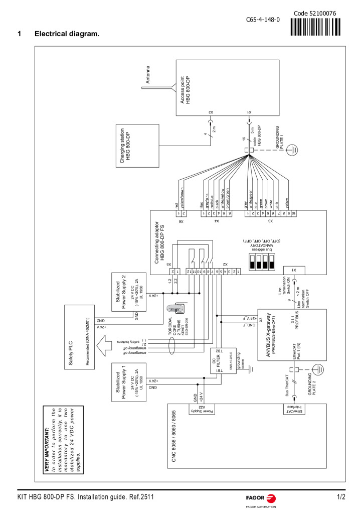
KIT HBG 800-DP FS. Quick Reference
PDF 0.2 MB · EN
Log in to download
New to the platform?
Create an account
·
