

Ask about this document
The AI answers using only this document and cites its pages.
AI Mode
Document preview
The answer was cut off before it finished.
You stopped the answer.
There are no documents for this question with the selected filters.
What went wrong?
Conversation about Fagor documentation
The answer was cut off before it finished.
You stopped the answer.
There are no documents for this question with the selected filters.
What went wrong?


Document contents
147 sections- ORIGINAL INSTRUCTIONS 2
- CONTENTS 3
- EC-DECLARATION OF CONFORMITY 7
- TÜV SÜD FUNCTIONAL SAFETY CERTIFICATE 9
- ABOUT THIS MANUAL 13
- ABOUT THE PRODUCT 14
- SHIPPING CONDITIONS, STORAGE, DECOMMISSION AND DISPOSAL 15
- VERSION HISTORY 17
- SAFETY CONDITIONS 21
- EC-DECLARATION OF CONFORMITY, WARRANTY TERMS AND QUALITY CERTIFICATES 24
- RECOMMENDED DOCUMENTATION 25
- 01| DESCRIPTION 27
- 1.1 Description 28
- 1.2 General Diagram 29
- 1.3 Stages of the System Configuration 30
- 1.4 Insulation Diagram of a Machine System 31
- 1.5 Environmental Conditions 32
- 1.6 Electrical Conditions 32
- 02| MAIN POWER SUPPLIES 33
- 2.1 Non-Regenerative Main Power Supplies 34
- 2.2 Regenerative Main Power Supplies 55
- 2.3 Regenerative Regulated Main Power Supplies 71
- 03| DRIVES 99
- 3.1 Modular Drives 100
- 3.2 Compact Drives 146
- 3.3 Turning a Drive On 184
- 04| AUXILIARY MODULES 187
- 4.1 Mains Filters 188
- 4.2 Chokes 191
- 4.3 External Braking Resistors 193
- 4.4 Capacitor Module. CM-1.75 198
- 4.5 Auxiliary Power Supply. APS-24 199
- 4.6 Bus Protection Module. BPM 203
- 05| SELECTING CRITERIA 207
- 5.1 Selection of the Synchronous Servomotor and its Associated Drive 207
- 5.2 Asynchronous Spindle Motor and Drive Selection 212
- 5.3 Main Power Supply Selection 218
- 5.4 Capacitor Module Selection Guide 228
- 5.5 Braking Resistor Selection Guide 229
- 06| POWER LINE CONNECTION 233
- 6.1 Mains Connection 233
- 6.2 Protection Fuses 235
- 6.3 Differential Breaker 237
- 6.4 Isolating Transformer or Auto-Transformer 238
- 6.5 Mains Filter 240
- 6.6 Line Inductance 241
- 6.7 Distribution Diagrams 242
- 6.8 Mains Connection Cables 246
- 07| CABLES AND ADAPTERS 247
- 7.1 Mains Connection Cable. Power Supply | Mains Connection 248
- 7.2 Power Cable. Motor|Drive connection 250
- 7.3 Motor Feedback Cables 252
- 7.4 Connector Adapter. CA-D1-D4 254
- 7.5 Direct Feedback Cable 255
- 7.6 Signal Cables for Control and Communications 257
- 7.7 RS232/RS422 BE Adapter 261
- 7.8 RS-232 Serial Line 262
- 7.9 RS-422 Serial Line 266
- 08| INSTALLATION 269
- 8.1 Location 270
- 8.2 Inductive Components 277
- 8.3 System Installation 278
- 8.4 Connection Between Modules 281
- 8.5 Power Supply Connections 297
- 8.6 Connection of the Control and Communications Signals 299
- 8.7 Check the Installation 318
- 09| FUNCTIONAL SAFETY 319
- 9.1 Main Characteristics of the Safety Functions 321
- 9.2 Drive Enable Input and AS1-AS2 Feedback Output 322
- 9.3 Fault Detection and Reaction 323
- 9.4 Design Requirements 325
- 9.5 Electrical Precautions 327
- 9.6 Residual Risks 328
- 9.7 Technical Data of the Safety Functions 329
- 9.8 Response Time of the Safety Functions 330
- 9.9 Cabling and Grounding 331
- 9.10 Commissioning 332
- 9.11 Maintenance, Repair and Analysis of Hazardous Events 333
- 9.12 Decommission and Disposal 335
- 9.13 Electrical Safety, Environmental Conditions and EMC 336
- 10| CONNECTION DIAGRAMS 337
- 10.1 SPD Modular Drive with FM7 Asynchronous Spindle Motor 338
- 10.2 AXD Modular Drive with FKM Synchronous Axis Servomotor 339
- 10.3 AXD Modular Drive with FXM Synchronous Axis Servomotor 339
- 10.4 AXD 2.50-S0-0-B-L Modular Drive with Linear Motor 340
- 10.5 SCD Compact Drive with FM7 Asynchronous Spindle Motor 341
- 10.6 ACD Compact Drive with FKM Synchronous Axis Servomotor 342
- 10.7 ACD Compact Drive with FXM Synchronous Axis Servomotor 343
- 10.8 ACD 1.25-S0-0-B-L Compact Drive with Linear Motor 344
- 10.9 Electrical Cabinet. Diagrams 345
- 10.10 Diagrams with a PS-33-L Main Power Supply 351
- 10.11 Diagrams with a PS-65A Main Power Supply 353
- 10.12 Diagrams with a PS-25B4 Main Power Supply 355
- 10.13 Diagrams with a XPS Main Power Supply 357
- 10.14 Diagrams with an RPS Main Power Supply 359
- 10.15 ACD/SCD Compact System Diagrams, SERCOS II Connection 361
- 10.16 ACD/SCD Compact System Diagrams, CAN Connection 364
- 10.17 AXD/SCD Mixed System Diagrams, SERCOS II Connection 366
- 10.18 AXD/SCD diagrams of a mixed system, CAN connection 367
- 10.19 Holding Brake Connection Diagram 369
- 10.20 On-the-fly Start/Delta Connection switching on FM7 Spindles, E03|HS3 Series 370
- 11| DIMENSIONS 371
- 11.1 Main Power Supplies 372
- 11.2 Auxiliary Power Supply 380
- 11.3 Modular Drives 381
- 11.4 Compact Drives 387
- 11.5 Bus Protection Module, BPM 390
- 11.6 Capacitor Module, CM-1.75 391
- 11.7 Mains Filters 392
- 11.8 XPS CHOKES 394
- 11.9 RPS CHOKES 395
- 11.10 External Braking Resistors 396
- 11.11 External Thermostat 398
- 12| SALES MODELS 399
- 12.1 Synchronous Servomotors 400
- 12.2 Asynchronous Motors 402
- 12.3 Modular Drives 403
- 12.4 Compact Drives 404
- 12.5 Positioning Drives 405
- 12.6 Power Supplies 406
- 12.7 Auxiliary Units 407
- 12.8 Cables 408
- 12.9 Order Example 410
- 12.10 Unit Identification 411
- 13| COMPATIBILITY 413
- 13.1 Mains Voltage 413
- 13.2 Compatibility 413
- 13.3 Module Replacement 414
- 13.4 VECON Board 414
- 13.5 VECON-2 Board 414
- 13.6 VECON-3 Board 415
- 13.7 VECON-4 Board 415
- 13.8 Boot for VECON-2 415
- 13.9 Boot for VECON-3 415
- 13.10 Boot for VECON-4 415
- 13.11 SERCOS Card (16 MBd) 415
- 13.12 CAN Board 416
- 13.13 CAPMOTOR-x Boards 416
- 13.14 VECON-x Boards 416
- 13.15 Feedback Type and CAPMOTOR-2 Board 417
- 13.16 Recognizing RPS Power Supplies 417
- 13.17 APS-24 Auxiliary Power Supply with PS, XPS or RPS 417
- 13.18 Power Supplies Compatible with FM9 Motors 417
- 13.19 AXD...- L Drives at 200-240 Vac 417
- 13.20 ACD/SCD...- L Drives at 200-240 Vac 417
- 13.21 AXD/ACD Drive GAP CTRL Board 418
- 13.22 Transfer of «*.mot» Files. Motor Table 418
Related documentation
See all in Manuals
CNCelite 8065 Cylindrical grinder manual (·G· model)
PDF 9.3 MB · EN

CNCelite 8065 Gear hobbing machine manual (·G· model)
PDF 3.4 MB · EN ES

CNCelite 8065 Surface grinding machine manual (·G· model)
PDF 3.5 MB · EN
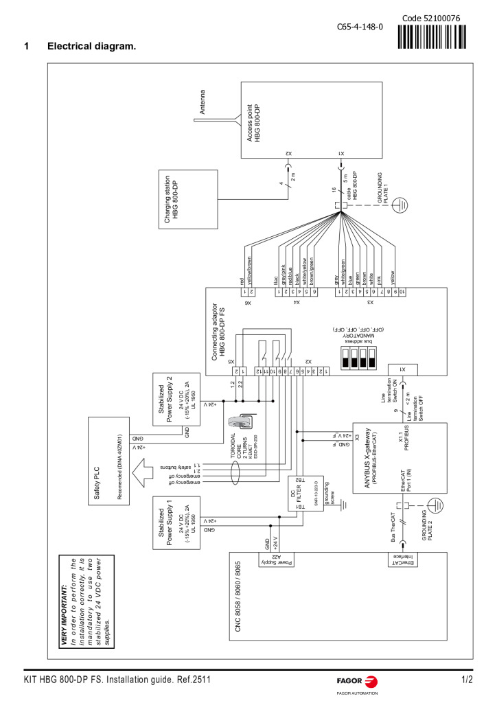
KIT HBG 800-DP FS. Quick Reference
PDF 0.2 MB · EN
Log in to download
New to the platform?
Create an account
·
