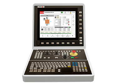
Cover: CNCelite 8065 Gear hobbing machine manual (·G· model)
CNCelite 8065 Gear hobbing machine manual (·G· model)
Manuals

CNCelite 8065 Gear hobbing machine manual (·G· model)

Document details

Format
PDF
Size
3.4 MB
Pages
38
Version
V1.0
Updated

Description

This manual provides comprehensive instructions for the CNC 8065 (·G· model) specifically configured for gear hobbing machines. It covers machine axis configuration, operation of the HOB Gear screen, cycle editing, and detailed procedures for axial, radial, and tooth-by-tooth hobbing cycles.

This guide is intended for machine operators and integrators to configure tools and execute specific gear hobbing cycles on the CNC 8065 (·G· model).

Document contents

54 sections
  1. INDEX 3
  2. 1. BASIC CONCEPTS. 5
  3. 1.1 General concepts. 5
  4. 1.2 Configuration of the machine axes. 5
  5. 2. BASIC OPERATIONS. 7
  6. 2.1 Main screen. 7
  7. 2.2 HOB Gear. 8
  8. 2.2.1 Activate HOB. 10
  9. 2.2.2 Add HOB. 10
  10. 2.2.3 Delete HOB. 10
  11. 3. CYCLE EDITING. 11
  12. 3.1 Accessing gear hobbing cycles. 11
  13. 3.2 Cycle editing. 12
  14. 3.3 Simulation or execution of a gear hobbing cycle. 12
  15. 3.4 Inserting a gear hobbing cycle into a program. 13
  16. 3.5 Execution or simulation of a program with gear hobbing cycles. 13
  17. 4. GEAR HOBBING CYCLES. 15
  18. 4.1 Axial. 15
  19. 4.2 Radial. 18
  20. 4.3 Radial + Axial. 21
  21. 4.4 Tooth by tooth Axial. 24
  22. 4.5 Tooth by tooth Radial. 27
  23. 4.6 Tooth by tooth Radial + Axial. 30
  24. 5. TOOL VARIABLES 33
  25. 5.1 List of variables from the technological tables. 33
  26. 5.1.1 Variable group "COMMON". 33
  27. 5.1.2 Variable group "GEOMETRY". 33
  28. INDICE 3
  29. 1. CONCETTI FONDAMENTALI. 5
  30. 1.1 Generalità. 5
  31. 1.2 Configurazione degli assi della macchina. 5
  32. 2. OPERAZIONI DI BASE. 7
  33. 2.1 Schermata principale. 7
  34. 2.2 Tabella frese. 8
  35. 2.2.1 Attiva fresa. 10
  36. 2.2.2 Aggiungi fresa. 10
  37. 2.2.3 Elimina fresa. 10
  38. 3. MODIFICA DEI CICLI. 11
  39. 3.1 Accesso ai cicli di fresatura. 11
  40. 3.2 Modifica di un ciclo. 12
  41. 3.3 Simulazione o esecuzione di un ciclo di fresatura. 12
  42. 3.4 Inserimento di un ciclo di fresatura in un programma. 13
  43. 3.5 Esecuzione o simulazione di un programma con cicli di fresatura. 13
  44. 4. CICLI DI FRESATURA. 15
  45. 4.1 Assiale. 15
  46. 4.2 Radiale. 18
  47. 4.3 Radiale + assiale. 21
  48. 4.4 Dente a dente Assiale. 24
  49. 4.5 Dente a dente Radiale. 27
  50. 4.6 Dente a dente Radiale + Assiale. 30
  51. 5. VARIABLES DE LA HERRAMIENTA. 33
  52. 5.1 Elenco di variabili delle tabelle tecniche. 33
  53. 5.1.1 Gruppo di variabili "COMMON". 33
  54. 5.1.2 Gruppo di variabili "GEOMETRY". 33

Technical data

Tool types
Gear hob, Modular (spur), One tooth cutter p. 8
Hobbing cycles
Axial, Radial, Radial + Axial, Tooth by tooth (Axial, Radial, Radial + Axial) p. 15
Tool data parameters
MN/DP, Pressure angle, Outside diameter, M3/M4, Teeth p. 8
Feedrate limits
Vmin, Vmax (m/min), Fmin, Fmax (mm/rev) p. 9

Data extracted from the document with AI and reviewed. Check the value on the indicated page.

Errors and alarms covered

CodeMeaningPage
Feedback alarm Alarm triggered for analog axes when safety elements are disabled. p. 2
Software limits Warning message for analog and sercos linear axes if software limits are disabled. p. 2
Following error Monitoring error for analog and sercos axes at the CNC and drives. p. 2
Tendency test Safety alarm related to the status of analog axes. p. 2

List extracted from the document with AI and reviewed; it does not replace the manual. See the indicated page.

See all in Manuals

Back to documentation

·